AIEX Deep Learning platform provides you with all the tools necessary for a complete Deep Learning workflow. Everything from data management tools to model traininng and finally deploying the trained models. You can easily transform your visual inspections using the trained models and save on tima and money, increase accuracy and speed.
So far we had 3 industrial revolutions, each reducing reliance on human labor and utilizing unmanned systems more than before, we believe the last major uncharted teritory in unmanned systems is the intelligence sub-systems and that’s the defining point of 4th industrial revolution.
Revolutionary Indsutry Transformation
So far we had 3 industrial revolutions, each reducing reliance on human labor and utilizing unmanned systems more than before, we believe the last major uncharted teritory in unmanned systems is the intelligence sub-systems and that’s the defining point of 4th industrial revolution.
Intelligent Defect Detection in Metal Parts using Optical System for Industry 4.0 Manufacturing
Converting conventional quality control (QC) units into intelligent and automated detection systems is a high priority for manufacturing professionals. Intelligent QC systems reduce cost and time in most production lines in various stages of production and significantly improve the quality of the final products. Traditionally, defects are detected by either human operators or computer models trained by time-consuming machine learning (ML) techniques.
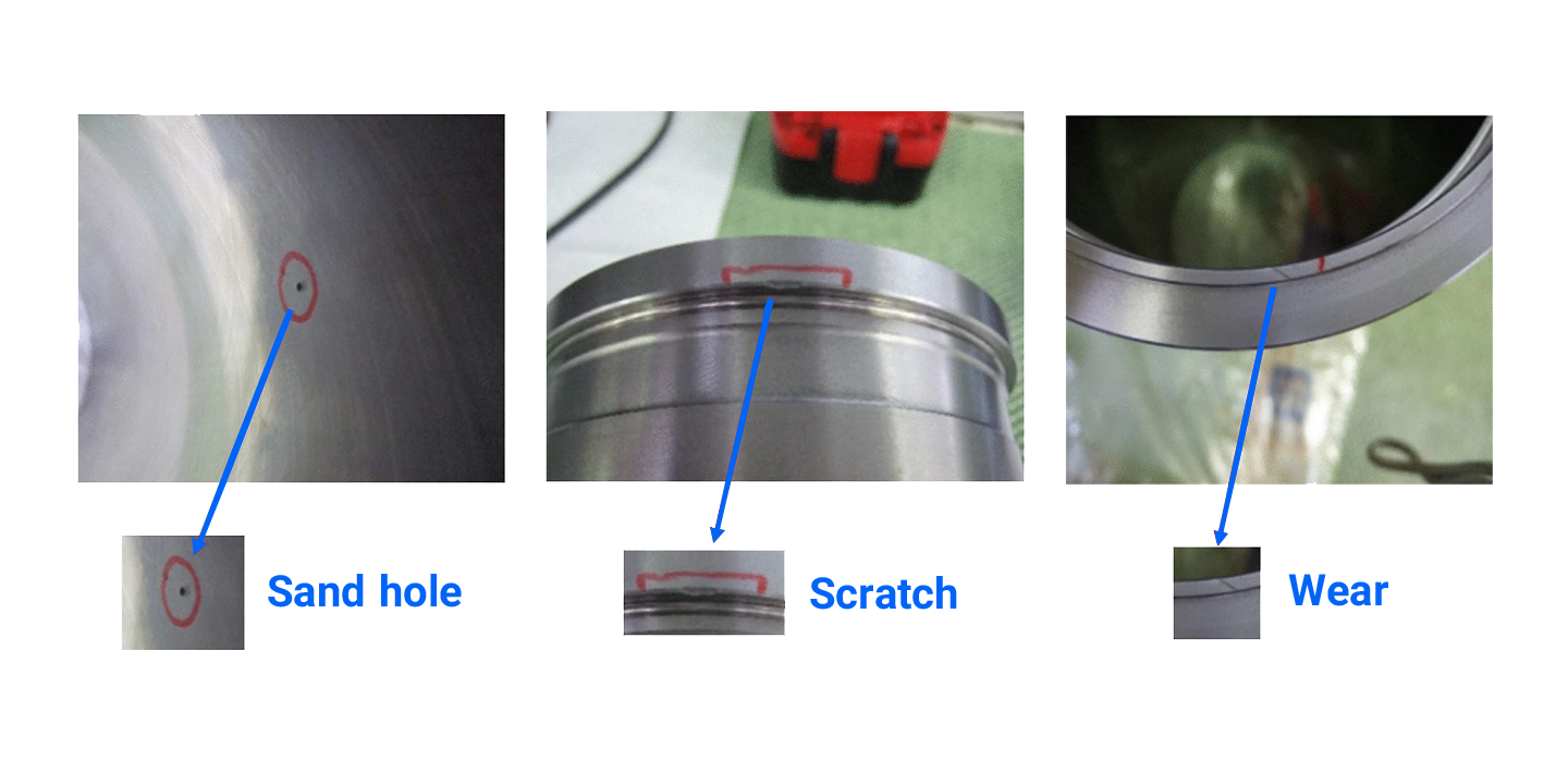
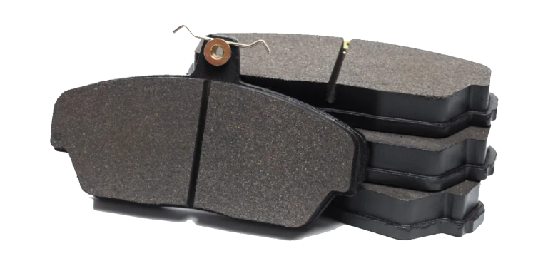
Papavasileiou et al. from the department of mechanical engineering and aeronautics at the university of Patras in Greece devised an automated optical system, which can detect and classify aesthetic defects in different sizes, shapes, and positions immediately after the casting process. Employing this approach eliminates the need for training and minimizes the required resources, resulting in a cost-effective solution with high flexibility in terms of introducing new parts/products of the same material in different stages of production(Figure 1). The authors published their results in the “international journal of computer integrated manufacturing”, 2022.
Figure 1. Various automotive parts can be controlled for defects using the proposed approach. Source
Computer vision (CV)-based solutions in-line with the industry 4.0 paradigm will be immensely helpful for the existing industrial processes and techniques. However, numerous efforts by engineers and researchers Have failed to meet the manufacturing requirements until now, particularly in the field of intelligent visual inspection systems. Defect detection immediately after the casting process involves three main approaches:
Visual inspection by human operators: Although this is the most common technique, it is highly prone to human error.
Non-destructive (ND) testing techniques: Ultrasonic inspection and radiographic examination are two accurate ND testing techniques. Their downside is the high price of the equipment required to implement them (e.g. laser scans) is quite high.
CV techniques and algorithms: These approaches consist of machine learning techniques, signal-processing methods, etc. Among them, CV techniques based on deep learning algorithms for identifying and classifying defects have garnered much attention since they offer excellent accuracy, low-cost operation, and a high level of automation.
Steel industries, for example, have used CV models to detect potential cracks on steel billet surfaces, monitor the surface of hot-rolled flat steel sheets, and inspect the trimmed edges of steel billets. Some image processing techniques such as Top-Hat filter and Hough transform have also been employed for defect detection in steel industries. In other industries, the brightness, contrast, or contours of images have been used to identify defects. Nevertheless, none of these models exhibited the required flexibility as they focus strictly on specific parts or processes and fail to generalize the solution.
Recently, deep learning approaches have been used to detect defects in hot-rolled steel. Surface defects have also been classified using Scale Invariant Feature Transform, and the use of Convolutional Neural Networks (CNN) in detecting welding defects has been investigated. A pre-trained AlexNet architecture has been utilized to classify black lines and wrinkle defects in leather images. Deep CNN algorithms based on TensorFlow have been applied to detect defects in wooden parts, the surface of solar cells, tungsten inert gas welding, steel wire ropes, cylindrical roller bearing components, etc.
Although the results of such studies are promising, some critical shortcomings still exist that limit their usage in real manufacturing settings. These issues include (i) the trained model’s accuracy for identifying and classifying aesthetic defects highly depends on the quality of training data and the labeling procedure. (ii) the amount of required data may differ and, in some cases, training should be performed from scratch. (iii) training a large, deep-learning model, requires high computational power resulting in a large carbon footprint.
The Workflow for Intelligently Detecting Defects in Metal Parts
The workflow of the proposed optical system consists of six steps:
Image acquisition
The selected camera captures appropriate images. This procedure is performed through the following steps:
Establishing a connection with the camera
Setting up the parameters of the data acquisition device, including a) width, b) height, c) offset in X-axis, d) offset in Y-axis, and e) exposure value
Obtaining the image
Storing the captured image
Image Pre-processing
Image pre-processing involves three steps:
Smoothing the image using Gaussian filters to remove excessive detail and noise
Creating regions of interest (ROI)
Calculating projections
Defects Detection
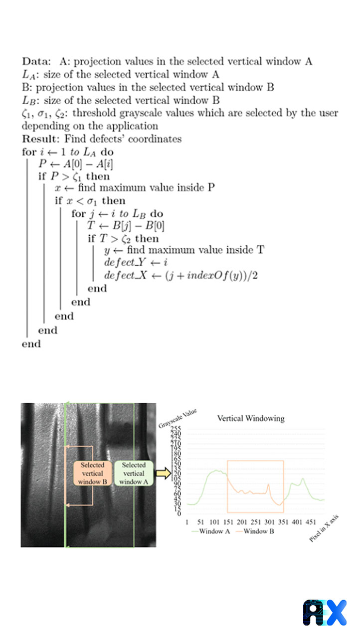
The authors propose an algorithm (Figure 2a) for detecting defects from selected vertical windows (Figure 2b) after the preprocessing step. The projections calculated in the pre-processing step are investigated using a custom sliding window search algorithm.
Figure 2. (a) the proposed algorithm for defect detection, and (b) selected vertical windows. Source
Signal processing consists of identifying peaks and valleys in the selected ROIs (Figure 3).
Figure 3. Projection values with a potential defect circled in red. Source
Image Classification
The coordinates of potential defects are obtained in the previous step. The acquired 2D images are classified based on the height and width measurements of each identified defect, which depends on the application’s requirements (Figure 4).
The obtained results from the previous steps are arrays of X and Y coordinates for each identified defect. These sets of coordinates are marked by visible circles inside the image, which can be communicated to the human operator using the Web Application UI.
System Implementation Architecture
The proposed optical system has been designed as a standalone application. Figure 5 shows the communication routes between the different layers.
The Presentation Layer includes the UI controller and the Web Application UI. The UI controller provides the image with marked defects in a graphical window before communicating it using the Web Application UI.
Service Layer
The Service Layer performs interface services including the communication traffic handler.
Logic Layer
The Logic Layer contains four components: (i) Acquisition Module: to activate the camera and capture 2D images, (ii) Pre-processing Module: to filter/smooth the image and calculate the required values, (iii) Detection Algorithm, and (iv) Classification Algorithm: the two latter components include the core detection and classification algorithms for identifying and classifying defects on the product surface.
Data Layer
This layer groups/models the data used by the optical system. Data models are only used for the internal operations of the application. Thus, an internal reverse connection between the Logic Layer and the data models (Data Layers) has been established.
Software Implementation
HDevelop13 and Pylon Viewer software applications were employed to calibrate the camera and the threshold values (Table 1). The proposed algorithms were implemented using the C# programming language inside Microsoft Visual Studio IDE. The optical system runs on a combination of C# and MATLAB scripts. The MVTec Halcon Library (“HALCON – Comprehensive Software for Machine Vision with an IDE) has been used to control the selected camera and process various data used for detection.
Table 1. Selected parameters
A user interface based on HTML5 principles has been deployed on top of a web application to display the results in devices like computers, tablets, and smartphones. Figure 6 shows the developed web UI.
Employing the Proposed Approach in the Automotive Industry
To evaluate the proposed approach for a real-life application, detecting aesthetic defects on the surface of metal parts for the automotive industry is considered as a case study. A set of 25 monoblock aluminum brake calipers are placed inside the field of view of a camera sensor one by one. An industrial robot manipulator has been used for automatic transportation (Figure 7). The brake calipers were mounted on the end effector of the robot manipulator, based on the caliper’s body geometry. A Basler 2D area scan camera (Ag 2020) equipped with Kowa lens (“Kowa 1” LM35HC Lens” 2020) is used to support exposure and focus calibration, and to capture images with a resolution of 3000 × 1700 pixels.
Figure 7. Experiment setup for implementing the automatic defect detection. Source
The connection between the camera and the PC has been accomplished using a network switch device (“Linksys Business LGS308MP PoE+ Smart 8 Port Gigabit Network Switch (130W)” 2020). Figure 8 depicts an overview of the connectivity between different components.
Table 2 presents and compares the results of implementing the proposed approach on 25 monoblock aluminum brake calipers. Defects are identified with a success rate of 95.9% with an averageexecution time of 52 seconds. The total error was 8.7% including either failure to detect actual defects (12 out of 22) or points wrongly interpreted as defects (10 out of 22).
Table 2. Experimental results.
Figure 9 demonstrates the identified defects in monoblock aluminum brake calipers using the proposed optical system.
Figure 9. Identified defects from the optical system. Source
Images are grouped into three categories based on the size of their defects:: (A) OK, (B) MINOR DEFECTS, and (C) NOT OK. The classification algorithm categorizes results with a success rate of 92%. The mean error for the identified defects’ height and width was 1.48mm and 1.53mm, respectively (Figure 10).
Figure 10. Classification accuracy for caliper images based on defects’ dimensions. Source
Table 3 presents and compares the detection and classification accuracy with other approaches. Hot-rolled steel plates and steel billets have been selected since their morphological state is similar, even though the presented metal caliper parts are proven to have even more difficult surface conditions. The proposed model exhibits a better performance in detecting actual defects for real applications.
Table 3. Comparison of the performance of the proposed model with other works
Conclusions and future work
The proposed approach improves the quality of inspection for finished products using a simple and cost-effective optical system under the scope of Industry 4.0. The proposed identification and classification algorithms have been successfully implemented in the automotive industry. The results prove that the optical system is fast and cost-effective, and exhibits high reliability for precisely identifying and classifying aesthetic defects without training a model. Additionally, the system is highly flexible and can be used to inspect the quality of different products from the same material.
Authors claim that the proposed approach can be applied in various industries and for different materials such as plastic, paper, food, etc. Furthermore, to achieve minimum execution time, the proposed approach should be implemented on a multithreaded basis. Finally, to automatically select suitable threshold values for various applications, more research should be conducted.
If you have any inquiries about how the AIEX platform can be used to train state-of-the-art models for intelligent defect detection in special cases, please do not hesitate to contact us.
Subscribe to our newsletter and
get the latest practical content.
You can enter your email address and subscribe to our newsletter and get the latest practical content. You can enter your email address and subscribe to our newsletter.